|


- News
A new method for data measurement of elevator guide rail
11/29/2020 7:32:36 PM
The installation of elevator guide rails is a very important part of elevator installation. The quality of guide rail installation directly affects the comfort and safety of elevator operation.
Traditional manual measurement of elevator guide rail data
The main problem of traditional manual measurement is that the accuracy of the measuring instrument is difficult to meet the requirements, and the use environment of the measuring tool is not consistent. During installation and inspection, the verticality of the guide rail is generally measured by a magnetic line drop with a calibration ruler, a steel ruler or a vernier caliper. Merely using an ordinary ruler as a measuring tool cannot meet the above accuracy requirements. According to the requirements of the specification for the use of vernier calipers, the distance between the magnetic line of force and the working surface of the guide rail cannot be accurately measured with vernier calipers. At the same time, the swaying of the magnetic field line during the measurement process, the placement of the vernier caliper and the reading error, etc., will cause large errors in the measurement results. And after the elevator installation is completed, in the actual gauge measurement process, there are often situations where the top surfaces of the guide rails are interfered by steel wire ropes or other car top components. Therefore, traditional manual measurement has shortcomings such as high measurement difficulty, low accuracy, and complicated operation.
A new method for data measurement of elevator guide rail
According to the current status of elevator guide rail data measurement, the main problems we face are the two major challenges of measurement accuracy and measurement convenience. Through long-term on-site inspections and in-depth communication with relevant personnel, the author proposes to rely on high-precision inclination sensors, supplemented by specially designed measuring tools, to form an accurate, efficient and convenient elevator guide rail data measurement method.
Compared with the traditional manual measurement and the existing special instrument measurement, the measurement method using the high-precision tilt sensor has the following advantages.
The high-precision tilt sensor is simple and convenient to operate, and the measurement accuracy can meet the requirements of national standards. And the inclination sensor is supplemented by the corresponding module, which can directly display the measurement data. After conversion according to the trigonometric formula, the size of the vertical deviation can be obtained. The required value can be quickly obtained through the relevant conversion table produced.
(3) Relying on the high-precision inclination sensor, making reasonable instrument shape and auxiliary parts, it can also measure the track coplanarity and gauge efficiently at the same time.
In the coplanarity measurement, the principle is the same as that of the existing special instrument. The instrument is equipped with a laser pointer and a receiving target. The instrument and the target are placed on the same side guide surface of the two opposite elevator guide rails as required. Read the value on the target and use the formula to calculate the coplanarity deviation.
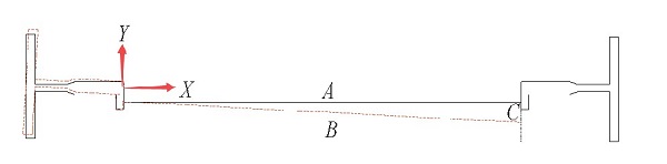
The gauge measurement is shown in Figure 1. In the actual field measurement, there is interference of the guide rail perpendicularity and the guide rail coplanarity on the gauge measurement. In terms of the perpendicularity of the guide rail, the perpendicularity is decomposed into two directions parallel to the working surface of the guide rail (X coordinate axis direction in Figure 1) and perpendicular to the working surface of the guide rail (Y coordinate axis direction in Figure 1). The component in the direction of the axis is the direct cause of the change in the gauge. The component in the vertical direction (Y-axis direction) does not exceed 1.2mm per 5m. The vertical component will make the laser beam hit the ideal zero scale on the receiving target. The deviation in the Y-axis direction can be obtained by converting the measured verticality of the rail according to the position of the measuring point on the rail. In terms of coplanarity, the centerline of the top surface of the guide rail is taken as the reference vertical line, and the instrument is artificially made at an angle with the horizontal plane in the direction of the plumb line. By reading an angle of a right triangle and the opposite side of this angle Length, get another right-angle side length. On the horizontal plane, a right triangle is formed by the straight line (line B in Figure 1), the coplanar deviation distance (line C in Figure 1) and the gauge (line A in Figure 1). Knowing the two sides of a right triangle, according to the Pythagorean Theorem, through conversion, the final accurate gauge value can be calculated.
Friend Link |
